


 English
TURN-KEY PCB ASSEMBLY: BITTELE ELECTRONICS
PCB MANUFACTURING AND ASSEMBLY
Full Turn-Key PCB Manufacturer
You can quickly get quotes and order PCB fabrication and assembly using our online system. Take advantage of exclusive automatic discounts with our tool. Our BOM pricing tool ensures you receive the lowest price for your order.
START A TURN-KEY PCB ORDER
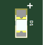
Indicating Diode Polarity
Pop quiz: which way should the diode be mounted during PCB Assembly, for the footprint shown to the right? Should the anode be at the top, or at the bottom? A lot of people would probably answer that the anode should face upward, toward the plus sign. Unfortunately, this is a trick question; it’s impossible to know simply from looking at this information. Let’s talk about why that is.
First of all, while it’s true that your average rectifier diode only allows for positive current flow from anode to cathode, there are other types of diode that don’t follow this simple rule. Zener and TVS diodes are often connected with their cathodes facing the more positive voltage. Past their breakdown voltages, these parts allow for reverse bias conduction, providing useful properties such as voltage regulation and transient attenuation.
This does not mean that Zener and TVS diodes are universally connected in reverse bias; rather, it depends upon the design in question. It should be clear at this point that the plus sign marking is ambiguous for these types of diodes.
In that case, could you answer our initial pop quiz if you could look at the Bill of Materials or other PCB Design Files for this board, and verify that D1 is neither Zener nor TVS? Still, the answer is no.
Other diode types, such as the Schottky and even the common rectifier diode, can also be connected with their cathodes facing the more positive voltage, as shown in the flyback circuit below.
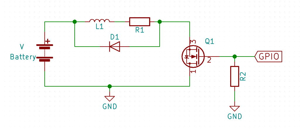
Commonly seen in circuits used to drive solenoids and other inductive loads, the diode D1 in the picture above is known as a Flyback Diode. When Q1 switches from saturation to cutoff mode, the energy stored in the magnetic field of L1 generates back EMF, or “Flyback”, which acts to maintain the flow of current that existed in the instant before Q1 switched off. D1 protects the switching element of the circuit from Flyback current by providing a safe path through R1 and L1.
The Flyback Diode is far from the only example of a standard diode type being connected with its cathode facing toward the higher DC voltage. It is simply a common example that is easy to explain and understand. Other common examples include H-bridges and battery backup circuits. In more complex PCB layouts, diode polarity is much more difficult to determine by circumstance alone. As such, it is important to include Clear LED and Diode Markings on the silkscreen layer of your PCB layout.
If you find yourself with any questions about clear labelling for your PCB project, feel free to reach out to one of Bittele’s PCB Customer Service Experts any time!
Related Articles:
Please briefly describe the information you are seeking in the search bar below.