


 English
TURN-KEY PCB ASSEMBLY: BITTELE ELECTRONICS
PCB MANUFACTURING AND ASSEMBLY
Full Turn-Key PCB Manufacturer
You can quickly get quotes and order PCB fabrication and assembly using our online system. Take advantage of exclusive automatic discounts with our tool. Our BOM pricing tool ensures you receive the lowest price for your order.
START A TURN-KEY PCB ORDER
How to create a Centroid File?
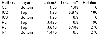
To place surface mounted parts on PCBs via automated equipment, it is necessary to create a Centroid file to program the equipment. A Centroid file contains all the positional parameters such that the machine knows where to place a component and in what orientation on a PCB. A Centroid file consists of the following information:
- Reference Designator (RefDes)
- Layer
- X location
- Y location
- Direction of Rotation
RefDes stands for reference designator. It will correspond to your bill of materials and PCB markup.
Layer refers to the top side or reverse side of the PCB or the side where the components are placed. PCB fabricators and assemblers often call the top and reverse sides the component side and solder side, respectively.
Location: the X and Y Locations refer to the values that identify the horizontal and vertical location of a PCB component with respect to the board's origin. The location is measured from the origin to the component's center. The board's origin is defined as the (0, 0) value and is located at the lower left corner of the board from a top point of view. Even the reverse side of the board uses the lower left corner as the origin’s reference point. The X and Y location values are measured to the ten thousandth of an inch (0.000).
Rotation is the direction of rotation of a PCB component's placement orientation referenced from a top point of view. The rotation is a 0 to 360 degree value from the origin. Both the top and reserve side components use a top point of view as their reference point.
The following are instructions for creating a Centroid file with different kinds of software:
- Run mountsmd.ulp to create the Centroid file.
You can view the file by going to the menu. Select File and then run ULP from the dropdown list. The software will quickly create the .mnt (mount top) and .mnb (mount reverse).
This file maintains the location of the components as well as the coordinates of the PCB's origin. The file is in the txt format.
This software is utilized to create the pick and place output that will be used in the assembly process. There are two options for creating the output
- Create an Output Job Configuration file (*.outjob). This will create a properly configured output generator.
- From the menu select File. Then from the dropdown list, click on Assembly Outputs and then Generates Pick and Place Files.
After clicking, OK, you will see the output in the Pick and Place Setup dialog box.
Note: The output created by the Output Job Configuration file is different from the output created by the Pick and Place Setup dialog box. The settings are stored in the config file when using Output Job Configuration file option. However, when using the Pick and Place Setup dialog, the settings are stored in the project file.
The procedure for creating a Centroil file for either Orcad or Allegro software is similar. From the menu, select File. Then, in the dropdown list, click on Export and Placement.
Note: This procedure correlates to the latest versions of Orcad and Allegro software. Previous versions may be different. Consult the user documentation for more information.
Related Articles:
Please briefly describe the information you are seeking in the search bar below.