


 English
TURN-KEY PCB ASSEMBLY: BITTELE ELECTRONICS
PCB MANUFACTURING AND ASSEMBLY
Full Turn-Key PCB Manufacturer
You can quickly get quotes and order PCB fabrication and assembly using our online system. Take advantage of exclusive automatic discounts with our tool. Our BOM pricing tool ensures you receive the lowest price for your order.
START A TURN-KEY PCB ORDER
How to Indicate Placement Orientation of Diodes and LEDs on PCBs
One of the most important aspects of PCB design is clear and consistent labeling. It is easy to get wrapped up in the details of the more complex portions of your board, but always be careful that you do not neglect clarity for the simpler, run-of-the-mill parts. At Bittele Electronics, our goal is to get every single PCB into your hands in perfect working order with the minimum PCB Turnaround Time. You might be surprised how much the indications built into your PCB itself can influence that turn time. Let’s take a look at the case of LEDs and other types of diodes.
Bittele’s industry-leading PCB Assembly Process builds verification into each and every stage of both PCB Fabrication and PCB Assembly. Part of our verification procedures include an early-stage DFM Check before we begin populating your bare boards with components. If our engineers run into any uncertainties or ambiguities, we always reach out to you for clarification before proceeding with the PCB Assembly Process. The communication to resolve these issues is normally very quick and efficient, but sometimes it can cost precious hours that could otherwise be spent working on your board. As such, it is always good practice to employ a clear labelling scheme on your PCB Silkscreen.
Diodes and LEDs can be particularly troublesome when it comes to clear indication of their polarity. To illustrate this point, simply ask yourself: which end of the diode should be connected to the more positive or more negative voltage? Well, is the diode used in a rectifier? Is it a Zener Diode? A TVS Diode? An LED? The point here is that the anode-cathode to positive-negative orientation depends upon the specific application for that diode.
It is convenient to have orientation information on the silkscreen of the PCB, making it easily visible during assembly. Below are some examples of clear, recommended markings as per our DFA Guidelines, as well as commonly seen ambiguous markings for your reference. All are shown cathode-up.
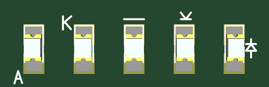
Clear, Recommended Diode Markings The diode Circuit Schematic symbol (far right) is the clearest option, but we understand that space might be a concern here. The head of the symbol, or even a simple line at the cathode will work for us. Many clients also use an A to represent the anode, or a K to represent the cathode. ‘K’ is used instead of ‘C’ in order to avoid confusion with Capacitors.
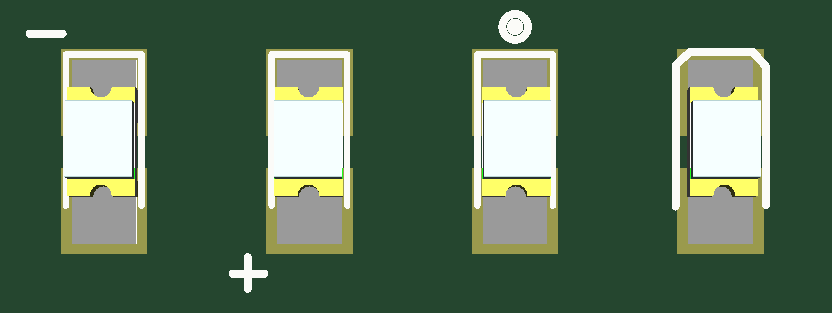
Ambiguous, NOT Recommended As explained in the paragraphs above, ‘+’ and ‘-‘ symbols do not necessarily line up with anode and cathode for all diodes, so they are not preferred. A dot or bent outline could easily indicate either anode or cathode, so it is also considered ambiguous, and will require confirmation.
Surface Mount Technology (SMT) diodes can be particularly tricky when it comes to proper orientation. It is common knowledge for electronics designers that the cathode of the device is the end that should be somehow marked, but manufacturers do not always follow this standard. While Through Hole Device (THD) variants are normally marked with a line at their cathode, or in the case of LEDs a flat edge or longer pin, surface mount diodes are notoriously inconsistent in this respect.
Below are excerpts from two datasheets that come from the same manufacturer. Both are describing white LEDs in the same PLCC-2 packaging, with very similar part numbers, and both use the same marking to indicate orientation. The difference? One part is marked at the anode, while the other is marked at the cathode.
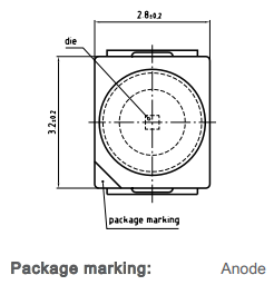
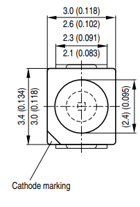
This sort of inconsistency even across the parts of a single manufacturer is one of the main reasons that Bittele’s Parts Procurement team never makes part substitutions without your direct approval.
For reasons such as this, it is always safest to include the manufacturer datasheet along with your PCB Design Files when you submit your order to Bittele for quotation. This way we can easily check for consistency between the markings on your silkscreen and the information in the manufacturer datasheet, in order to ensure your parts are installed properly the first time.
Related Articles:
Please briefly describe the information you are seeking in the search bar below.