


 English
TURN-KEY PCB ASSEMBLY: BITTELE ELECTRONICS
PCB MANUFACTURING AND ASSEMBLY
Full Turn-Key PCB Manufacturer
You can quickly get quotes and order PCB fabrication and assembly using our online system. Take advantage of exclusive automatic discounts with our tool. Our BOM pricing tool ensures you receive the lowest price for your order.
START A TURN-KEY PCB ORDER
How To Set Zero Orientation for Your Custom Footprints
Zero Orientation is a concept that rears its head rather infrequently in discussions of PCB Assembly, but one that tends to create significant confusion when it does appear. At its core, zero orientation is a rather simple concept, but it has the potential to cause confusion, delay, and even possible error during PCB assembly if it is entirely neglected. In order to provide clients of Bittele with a clear understanding of Zero Orientation, this article will start from the beginning, defining zero orientation in a thorough and robust manner, and explaining how to manage this attribute in your own PCB designs.
One of the core PCB Design Files is the Centroid, also known as the Pick & Place or X-Y Coordinates file. The centroid includes both placement and rotation data for each part to be included on your PCB, and is fed directly into Bittele’s Automated PCB Assembly machinery during the PCB Assembly Process. As such, it is nothing short of absolutely critical that a client’s centroid data is accurate and well-formatted, in order to ensure a High Quality PCB Assembly. For designs that include only standard library component footprints, centroid data will not require much attention from the PCB designer, for the most part being handled internally by the CAD software package. For PCB designs including custom footprints, on the other hand, you might need to pay some special attention to the manner in which rotation data is specified in your centroid file.
These rotations are normally based on one of two standards, specified by IPC’s planned revision C to their 7351B standards and described below:
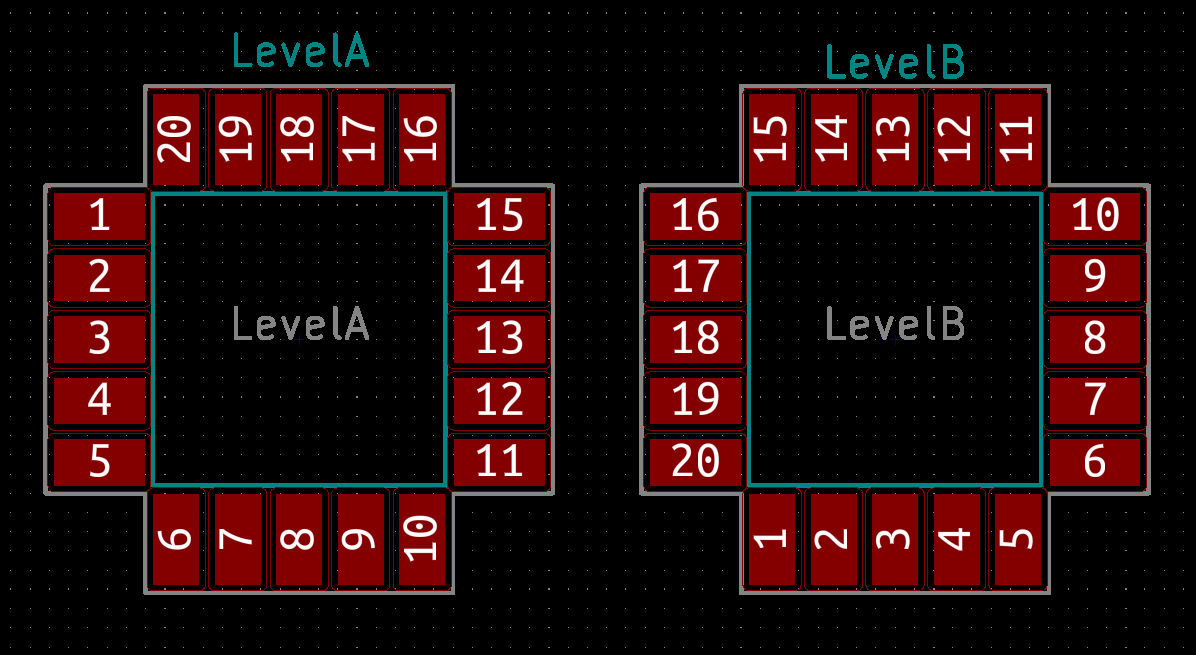
- Level A: Pin 1 in upper-left-hand corner of package when Rotation = 0
- Level B: Pin 1 in lower-left-hand corner of package when Rotation = 0
Bittele can handle either of these two standards, and we are also able to determine the zero orientation used during design by examining the centroid file and comparing against Gerber files or assembly drawings. That being said, specifying this parameter clearly in the assembly drawing or Gerber notes for a project can help to speed up the pre-assembly DFM Check process. The important thing to note here is that the two standards are incompatible with one another; a PCB design for automated assembly cannot incorporate parts with different zero orientations.
By way of example, the two footprints shown in the image below will both show a rotation value of zero in the Centroid file. They might look identical in many ways, but these are two distinct footprints that were designed separately in the footprint editor. The difference is that the pads were simply labelled in a different order for each footprint; we will return to this point in just a moment.
| Ref | Val | Package | PosX | PosY | Rot | Side |
|---|---|---|---|---|---|---|
| LevelA | LevelA | ZeroOrientationA | 102.87 | -95.885 | 0 | top |
| LevelB | LevelB | ZeroOrientationB | 122.555 | -95.885 | 0 | top |
It should be rather apparent from the image and centroid data above why these two standards are mutually incompatible. The two parts in the image above clearly require a different rotation, but the centroid data does not reflect this difference. A pick and place machine would assemble these two parts with the same orientation if this error was not caught in advance.
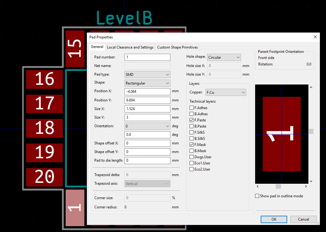
The vast majority of standard library component footprints use Level A zero orientation, so this standard is more familiar and comfortable to most PCB designers. In fact, many designers tend to use Level A orientation without even realizing it, perhaps even being unaware of zero orientation in general. As mentioned briefly above, the zero orientation for a custom part is determined by the order in which that component’s pads are labelled in the footprint editor of your CAD software. Zero orientation can be modified by editing an existing footprint and simply changing the pin numbers appropriately, as shown in the image below.
Finally, it should be noted that Level A and Level B orientation standards only apply to parts with more than 2 pins. For two-pin parts, such as resistors and capacitors, pin 1 should always be on the left at zero orientation.
If you find yourself with any further questions about the topic of zero orientation, or to send us your files for an official quotation today, please feel free to Contact Us any time! We can be reached via email at sales@7pcb.com, or toll-free at 1-888-812-1949.
Related Articles:
Please briefly describe the information you are seeking in the search bar below.