


 English
TURN-KEY PCB ASSEMBLY: BITTELE ELECTRONICS
PCB MANUFACTURING AND ASSEMBLY
Full Turn-Key PCB Manufacturer
You can quickly get quotes and order PCB fabrication and assembly using our online system. Take advantage of exclusive automatic discounts with our tool. Our BOM pricing tool ensures you receive the lowest price for your order.
START A TURN-KEY PCB ORDER
Rigid-Flex Printed Circuit Boards
In recent years, the prevalence of flexible printed circuit board technology has seen a considerable surge, in large part due to its benefits in the growing fields of wearable electronics, complex and High Density Interconnect (HDI) devices, and personal medical electronics . At Bittele Electronics, we always make sure to stay ahead of the curve when it comes to trends in the PCB industry, and we want to ensure that our clients have the information they need to do the same. In that interest, this article is intended to help our clients get an idea of Bittele’s capabilities when it comes to Rigid-Flex PCB Fabrication and PCB Assembly.
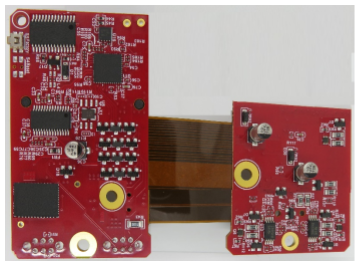
First, to cover the basics: a Rigid-Flex PCB describes a standard rigid board of FR-4 or other standard PCB Laminate Material, which is attached during the PCB Assembly Process to a thin, flexible PCB of R-F775 material. This flexible portion can be used to connect the main rigid PCB to other rigid “daughter boards” during the PCB Assembly Process, to connect into another device entirely post-production, or sometimes simply to satisfy space or shape constraints.
Bittele Electronics is happy to offer Complete PCB Assembly for Rigid-Flex PCB designs at the same level of quality and confidence that we provide our standard Turnkey PCB solutions. Our basic manufacturing capabilities for the flexible portion of the boards do differ somewhat from our capabilities where it comes to purely rigid boards, due to the delicate nature of these Flex-PCB solutions. For reference, please see our basic parameters outlined below:
| Layer counts | 1 to 4 Flex Layers |
|---|---|
| Finished PCB Size | 220 x 500 mm (8.66 x 19.68 inch) |
| Finished PCB Thickness | Minimum 0.07 mm for single layer
Minimum 0.13 mm for 2-layer |
| Finished Copper Weight | 0.5 oz. to 2.0 oz. |
| Dimension Tolerance | ±0.15 mm |
| PCB Partial Surface Finish | ENIG (others require special analysis) |
| Minimum Trace/Space | Same as standard Rigid PCB (see our DFM Guidelines) |
| Coverlay Colour | Amber (yellow), Black |
| Bend Radius | Approx. 15 to 20 times the Board Thickness |
| Rigid-Flex Interface Spacing* | Minimum 1.0 mm (discussed below) |
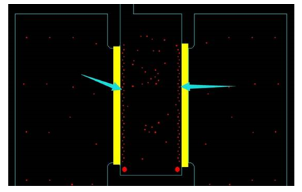
It is important to note the requirement listed in the final row of this table, since it is the most commonly overlooked aspect of Rigid-Flex PCB production, and as such results in the most concerns during initial quotation stages. Simply put, Bittele’s process for adhering the flexible PCB to the rigid PCB requires at least 1.0 mm of rigid PCB at the interface that is entirely free of via holes or other obstructions. The image below shows a rigid-flex design with vias placed directly along the edge of the rigid-flex interface, and our suggested extension of the rigid area to correct this issue.
With rigid-flex PCB designs growing in popularity and demand by year-by-year, Bittele Electronics is proud to offer robust solutions in this exciting area of PCB design and production. We do hope that this article will help our clients to better understand our processes, enabling you to improve your Design for Manufacturing (DFM), allowing for an even stronger partnership with Bittele.
If you still do find yourself with any concerns or questions for us with regard to an upcoming Rigid-Flex PCB project, or to provide your PCB Design Files for an official quote, please Contact Us today! We can be reached over email at sales@7pcb.com, or toll-free over the phone at 1-888-812-1949.
Related Articles:
Please briefly describe the information you are seeking in the search bar below.