


 English
TURN-KEY PCB ASSEMBLY: BITTELE ELECTRONICS
PCB MANUFACTURING AND ASSEMBLY
Full Turn-Key PCB Manufacturer
You can quickly get quotes and order PCB fabrication and assembly using our online system. Take advantage of exclusive automatic discounts with our tool. Our BOM pricing tool ensures you receive the lowest price for your order.
START A TURN-KEY PCB ORDER
What is a Gerber File? How to Generate Gerber Files
Gerber files are the industry-standard format for PCB Design Submissions. Since different PCB designers use a variety of different CAD software packages to create their PCB layouts, it is useful to have one common file type for use in PCB Fabrication. In order to promote efficiency, Bittele Electronics asks that all of our clients submit their designs in Gerber RS-274X or ODB++ format. This article is intended to assist our clients with the generation of Gerber files, and also to give some insight into the basics of the Gerber file format itself for those who might be unfamiliar.
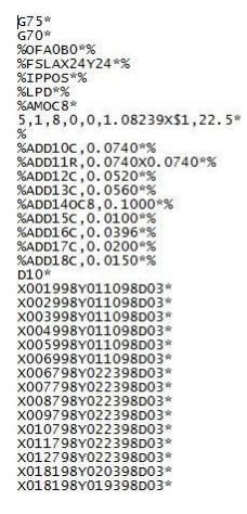
At their core, Gerber files are a simple ASCII format that contain operational commands with accompanying coordinates in X-Y position format. Gerber files are used to drive photoplotter machines for PCB Fabrication, and also for testing and Quality Assurance procedures such as Automated Optical Inspection (AOI). The image below shows an example of a simple Gerber file in terms of its raw data.
All common PCB design CAD software packages should include an option for generating Gerber files based upon your specified layout. This process is similar for most CAD tools, but to make the process as easy as possible, you can find Bittele’s tutorial articles below, where we explain in detail the Gerber generation process for various software suites.
How to Export Gerber Files from Eagle
How to Generate Gerber Files from KiCAD
How to Generate Gerber Files Using Altium Designer
How to Export Gerber Files from AutoCAD
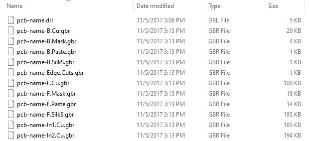
When you export your Gerber files, you should end up with one file for each copper layer of your board, and additional files describing the required Solder Mask, Solder Paste, and Silkscreen. During the Gerber file generation, you should also export your NC Drill files to describe any holes that should be drilled in the PCB, as well as the PCB Centroid File if you require Automated PCB Assembly. When the export is finished, you should end up with a collection of files that looks something like the image below:
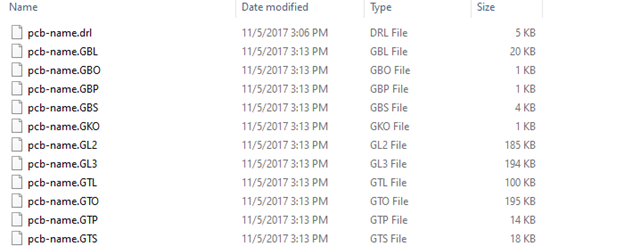
It should be noted that, while GBR is the default file extension for Gerber files, some CAD software packages identify the various Gerber layers by changing GBR to a different identifying extension. There is no reason to worry if you see file extensions like the ones below when you export your files:
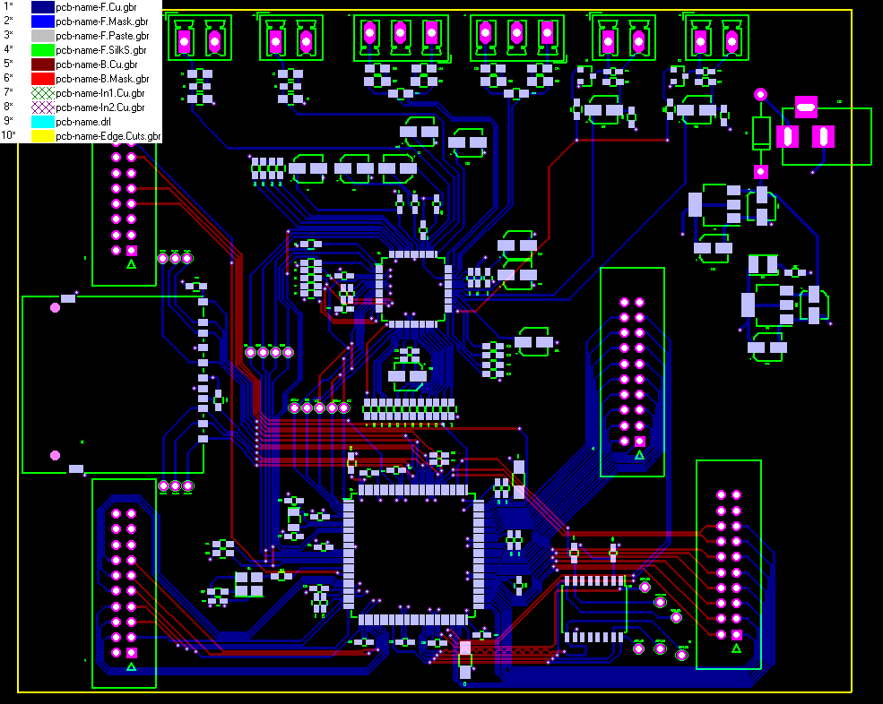
The specific version of Gerber files that we use at Bittele is called Gerber RS-274X, also known as extended Gerber or X-Gerber, which is a two-dimensional bi-level vector image description. The term “image description” refers to the fact that the Gerber file is not itself an image, but contains commands for effectively drawing a two-dimensional image, such as Line Draw, Flash, and Outline Fill. Certain Gerber Viewer software packages can translate the Gerber file into an image on your screen so that you can ensure no error occurred during the generation process. The following image shows the Gerber Viewer display for the files shown in the previous step.
If you have any further questions about the Gerber files for your project, or to send your Gerbers and other PCB Design Files to Bittele for an official quotation, you can feel free to Contact Us any time!
Related Articles:
Please briefly describe the information you are seeking in the search bar below.