


 English
TURN-KEY PCB ASSEMBLY: BITTELE ELECTRONICS
PCB MANUFACTURING AND ASSEMBLY
Full Turn-Key PCB Manufacturer
You can quickly get quotes and order PCB fabrication and assembly using our online system. Take advantage of exclusive automatic discounts with our tool. Our BOM pricing tool ensures you receive the lowest price for your order.
START A TURN-KEY PCB ORDER
Best Practices for Plated Slots
We see a lot of different footprints and component types for PCB Assembly at Bittele Electronics. A majority of through-hole part footprints are designed with circular holes to accommodate circular or square leads. This configuration is ideal for most through-hole components, but many parts incorporate rectangular or “blade”-style leads, which do not fit well into circular or square holes; instead, it is best to use a plated slot footprint. To illustrate this point, the image below shows a common barrel power connector with four thin rectangular leads fit into two different footprint styles.
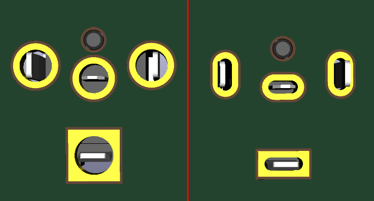
The footprint on the left in this image clearly leaves much more empty space around the component leads, where the image on the right provides a snug fit. This makes the circular hole configuration much more prone to common PCB Assembly defects such as solder joint voiding, since more solder is required to fill the holes.
These concerns become more significant as the size of the pins increases, from both design and production perspectives, so large blade-style connectors should definitely use plated slots rather than circular holes. At Bittele, we can still work with circular holes for rectangular pins when the part is relatively small, such as the standard barrel power connector used in this example. That being said, the circular holes do also take up more space on the PCB itself, and using plated slots can often help in size-restricted designs.
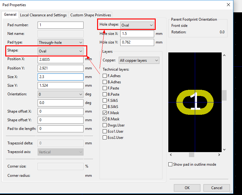
For the design of non-circular holes, a few things must be considered, but the process is fairly straightforward overall. It should first be noted that slots can be defined as plated through holes (PTH) or non-plated through-holes (NPTH). PTH slots are most often used in component footprints, and most PCB layout CAD programs provide an option in their footprint editor to define a hole as circular or oval. This will be enough for Bittele’s PCB Fabrication team to recognize the hole and use the correct process, but for extra clarity, some clients also indicate slot holes on a fabrication layer of their Gerber files.
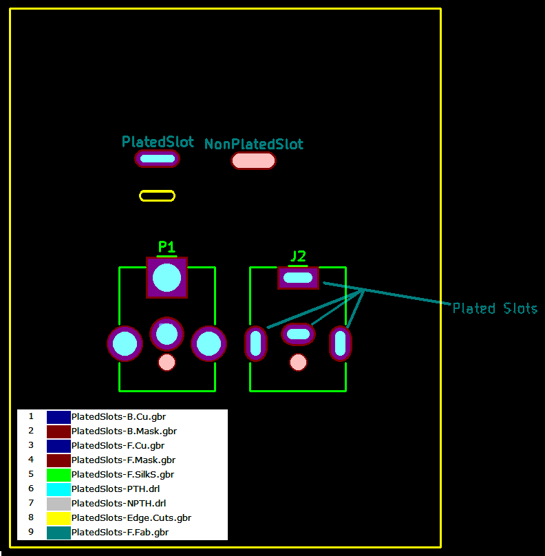
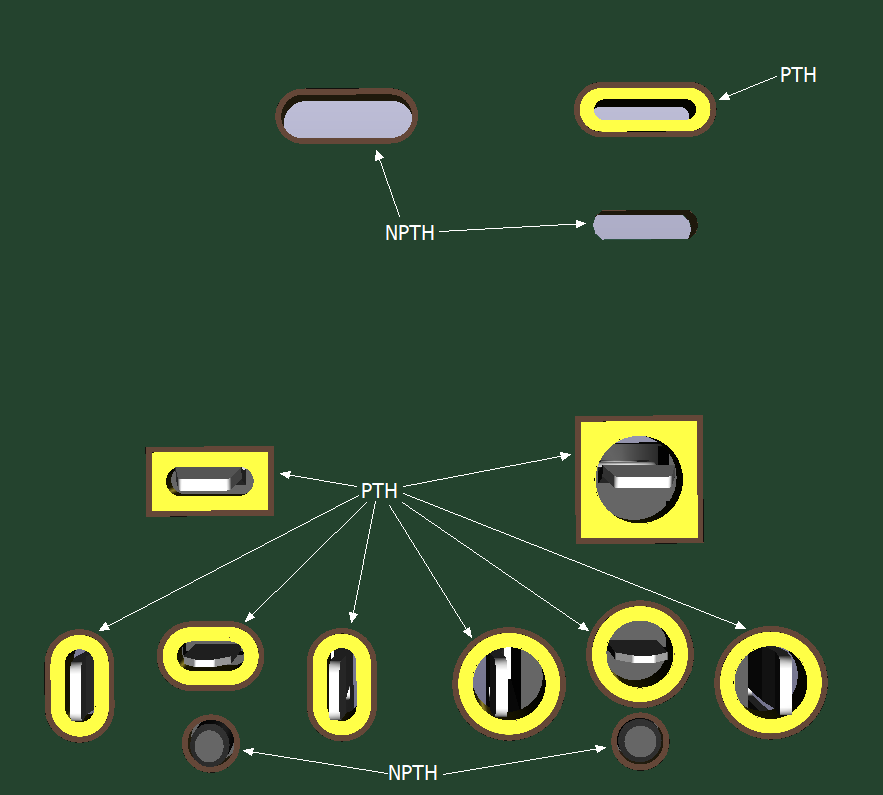
NPTH Slots can be designed in the same manner, and simply designated as NPTH / Mechanical in the CAD software, or they can be designed on the Board Outline Gerber layer. The following images show multiple options for both PTH and NPTH slots, first in a Gerber file view and then a 3D rendering of the resulting board.
If you have a question about hole shapes or sizes in your design, please feel free to Contact Us at any time and ask one of our PCB experts. With our flexible PCB Fabrication process at your disposal, never again will you need to fit a square peg in a round hole.
Related Articles:
Please briefly describe the information you are seeking in the search bar below.