


 English
TURN-KEY PCB ASSEMBLY: BITTELE ELECTRONICS
PCB MANUFACTURING AND ASSEMBLY
Full Turn-Key PCB Manufacturer
You can quickly get quotes and order PCB fabrication and assembly using our online system. Take advantage of exclusive automatic discounts with our tool. Our BOM pricing tool ensures you receive the lowest price for your order.
START A TURN-KEY PCB ORDER
How to Generate Gerber Files Using Altium Designer
For clients using Altium Designer, this guide will help you configure and output Gerber files as well as NC Drill files in RS274X format. It is assumed that you have finished designing your schematic as well as PCB layout. You should have both a .SchDoc file (schematic) and a .PcbDoc file (PCB layout) at this stage.
Generating Gerber Files
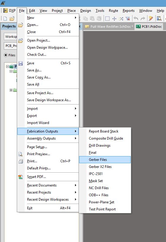
First, navigate to “File” tab at the top left corner of the program window. Next select “Fabrication Outputs” and in that drop-down menu select “Gerber Files”.
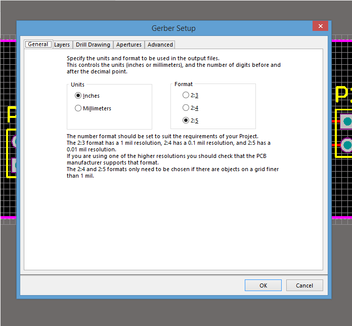
Once Gerber Files is selected the window below will appear which will allow you to specify the units and number digits before or after the decimal point.
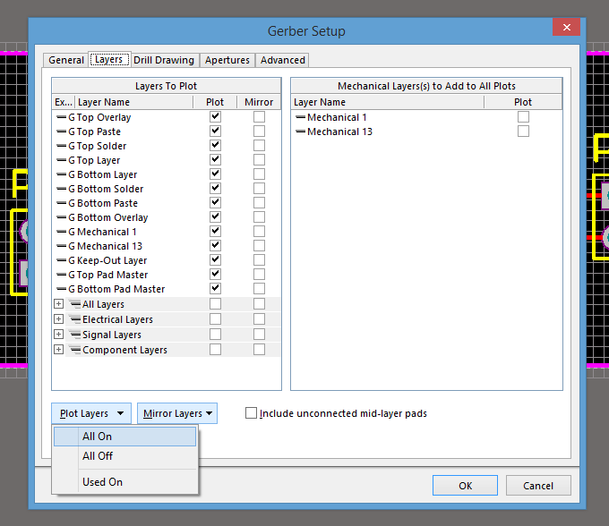
Next, using the tabs at the top of the window, navigate to the “Layers” tab. This will allow you to select which layers will be used for the output gerber files. If you are unsure which layers will be used, select the “Plot Layers” tab in the bottom left of the window and click “All ON” so it is highlighted. This will select all possible layers in the project for output.
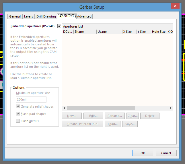
Afterward, using the tabs at the top of the window again, navigate to the “Apertures” tab. While in this window, ensure that the “Embedded Apertures (RS274X)” box is checked. The rest of the window can be left in its default settings.
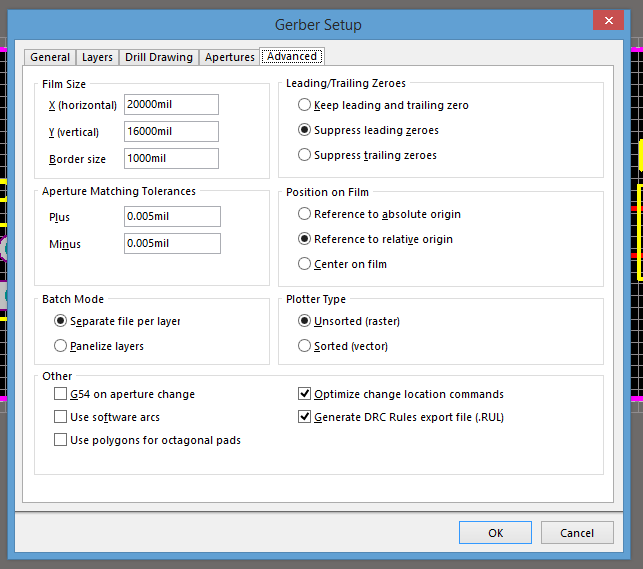
Finally, once again using the tabs at the top of the window, navigate to the “Advanced” tab. The settings in this window can be left default unless your design has special requirements. When you are finished press “Ok” in the bottom right of the window which will begin the output process for your gerber files.
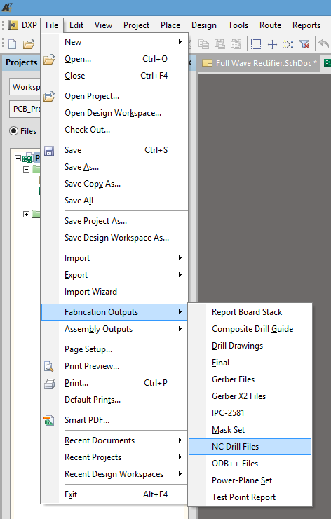
Once your main layer files are completed you need to output your NC Drill files. When fabricating your PCBs, these files indicate the size and placement of the holes which will be drilled for vias, mounting points, etc. First, return to the top left of the program and select “File”. In the drop-down menu select “Fabrication Outputs” and then “NC Drill Files”.
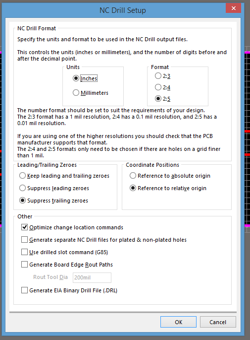
The previous step will open up the NC Drill File setup window. This will allow you to specific units and the number of digits before or after the decimal. This window can be left default unless your project requires specific parameters.
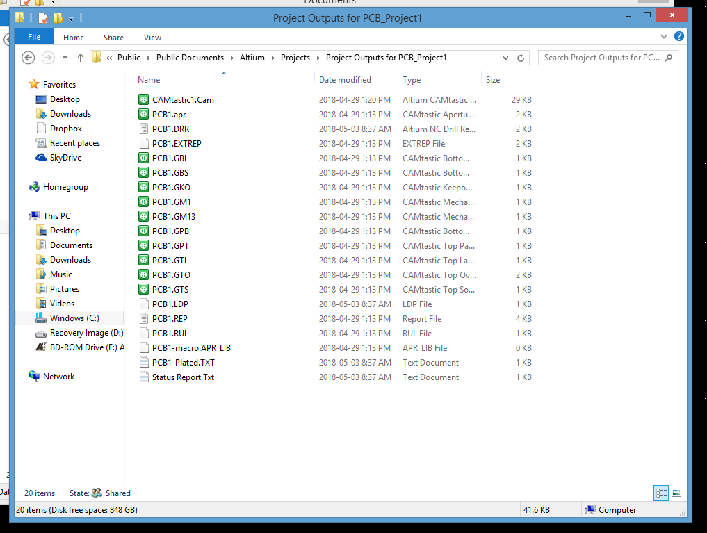
Finally, if you have saved all your files in one location you should have a similar number of files as shown in the picture below. Remember when submitting your files, it is best to compress the files in a .zip file to ensure they remain grouped together.
If you still find any steps involved in this process, please do not hesitate to contact a member of the Bittele Electronics sales team by sending an email to sales@7pcb.com, or calling our Toronto office at 1-416-800-7540. We are happy to help with any questions or concerns you may have and we look forward to working with you.
Related Articles:
Please briefly describe the information you are seeking in the search bar below.