


 English
TURN-KEY PCB ASSEMBLY: BITTELE ELECTRONICS
PCB MANUFACTURING AND ASSEMBLY
Full Turn-Key PCB Manufacturer
You can quickly get quotes and order PCB fabrication and assembly using our online system. Take advantage of exclusive automatic discounts with our tool. Our BOM pricing tool ensures you receive the lowest price for your order.
START A TURN-KEY PCB ORDER
How to Export Gerber Files from Eagle
The purpose of this document is to assist Bittele’s clients in the process generating Gerber filesusing the software suite known as Eagle. Bittele asks that its clients supply their PCB design files in thisformat because Gerber is the industry standard file type, and is therefore easily recognized andprocessed by our manufacturing equipment. We at Bittele recognize that this procedure may not befamiliar to all of our clients, and so we will proceed with a step-by-step description in the followingsection.
Generating Gerber Files
This guide assumes that you have finished designing your PCB within Eagle, and that you have astored file in the .brd format. We must extract Gerber files from the .brd file using Eagle’s Cam Processorsoftware. Steps for this extraction are outlined below:
1. Open the control panel for Eagle
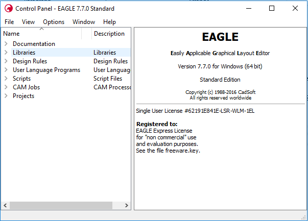
2. Select , and navigate to the .brd file that you would like to work with
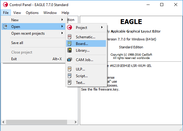
3. A window showing the PCB layout should now appear, as shown below:
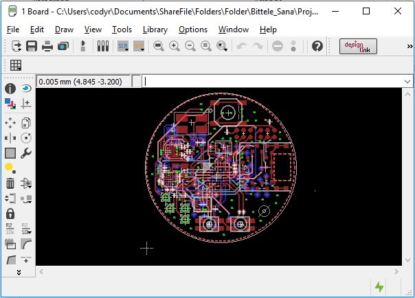
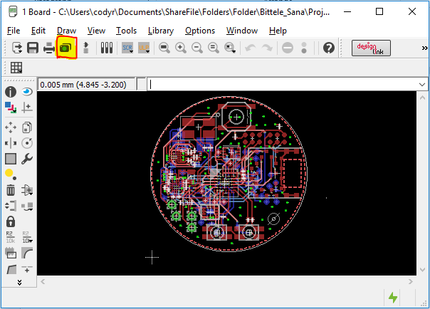
4. Select the camera icon from the top ribbon (highlighted below), or select
5. A new window will appear for the Cam Processor. In this window, select , as shown:
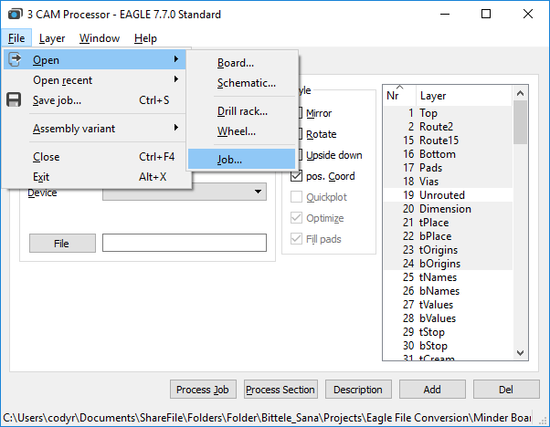
6. Select gerb274x-mill-drill.cam. This job file is set up for a 2-layer board, but the followingexamples show how to specify additional layers with the job if you so require.
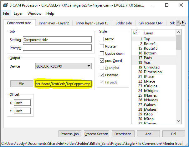
7. In the section of the Cam Processor window, select the button, and navigate to thelocation in which you would like to store the converted Gerber files. Choose a file name for thelayer, for example: the Component Side tab could have the file name “TopCopper.cmp”
8. If the board is greater than 2 layers, we must use the button in the bottom-right corner ofthe window to duplicate one of the existing copper layers, and modify its settings.
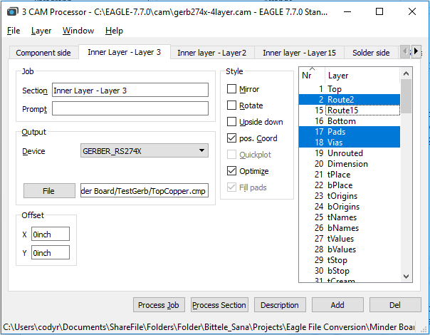
9. Re-name this layer in the field of the section, then choose the copper layer that itrepresents from the scrolling list at the far right of the window. For a regular inner copper layer,you should only need to select the copper layer itself ( in above picture), the , andthe .
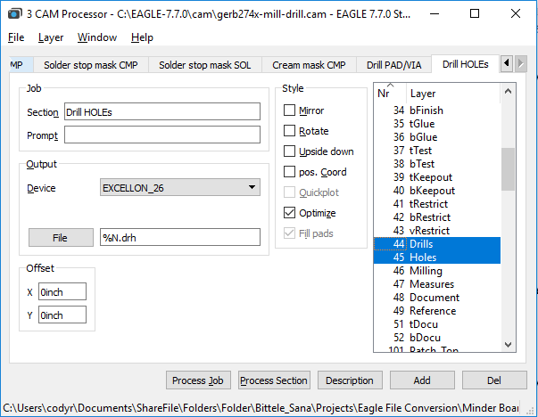
10. Now for the drill files; first choose the tab called , and ensure that the layer and the layer are selected (these are not selected by default). Also scroll down toensure that the layer is selected, although this one should be selected by default.
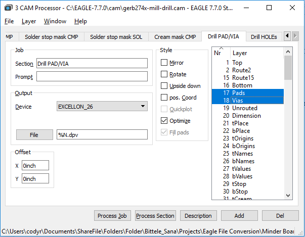
11. Next, choose the tab called , and scroll down in the layers list to ensure that boththe layer and the layer are selected. (Holes is selected by default, but not Drills)
12. Once you have specified File destinations for each of the tabs within the Cam Processor window,select the button at the bottom of the window.
13. Check the file path that you specified in step 7 to ensure that your Gerber files have beengenerated successfully. If you have access to a Gerber Viewer software, you can use it now toverify that the contents of your design files were preserved through the conversion procedure.
Drill File Secondary Option
If you already have the Gerber files, and simply need to export your PCBs drill files on their own,then worry not! The process for this is actually quite straightforward; it incorporates only four (4) steps:
1. From the Board view of your .brd file, select
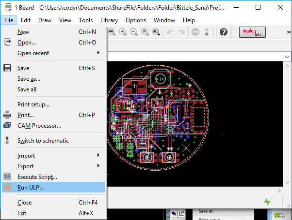
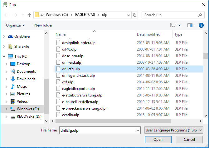
2. Choose the file called
3. Select the measurement units for your drill file. These should match with the measurementunits you specified during the design phase for this board. Select .
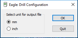
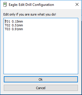
4. Select on this screen. Do not edit the text in this window unless you are absolutely certain ofwhat you are doing
5. Choose a file location for your drill files, and that’s it, you have successfully exported yourGerber files!
This guide’s aim has been to describe the procedure for generating Gerber files as simply andcompletely as possible. If you still find yourself unclear on any part of the process, please do not hesitateto contact a member of the Bittele sales team by sending an email to sales@7pcb.com, or calling ourToronto office at 1-416-800-7540. We are happy to help with any of your queries.
Related Articles:
Please briefly describe the information you are seeking in the search bar below.