


 English
TURN-KEY PCB ASSEMBLY: BITTELE ELECTRONICS
PCB MANUFACTURING AND ASSEMBLY
Full Turn-Key PCB Manufacturer
You can quickly get quotes and order PCB fabrication and assembly using our online system. Take advantage of exclusive automatic discounts with our tool. Our BOM pricing tool ensures you receive the lowest price for your order.
START A TURN-KEY PCB ORDER
Fiducial Mark for PCB Assembly Alignment
The alignment mark, commonly called the Fiducial Mark, is the reference position used on assembly machines such as a paste printing machine or a pick-and-place machine to ensure a precise PCB assembly operation.
The designer must follow some restrictions for drawing fiducials marks on a PCB layout to ensure they are recognized by a machine’s visual system. These restrictions include:
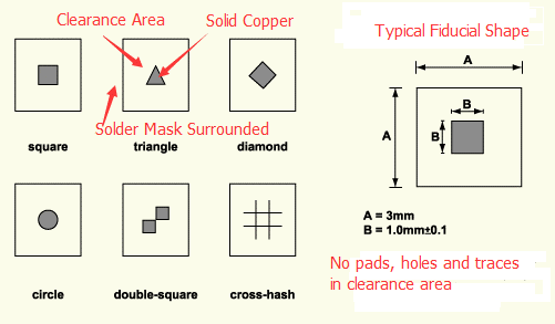
- The fiducial should be a solid filled object such as copper with same finishing as the other layout artwork in same PCB layer.
- There are lots applicable shapes of fiducial marks such as circles, squares, triangles, diamonds, double-squares and cross-hashes. But most popular one is a circle.
- The minimum diameter of a circular fiducial mark is 1 mm with 3mm dia. clearance area.
- No other pads, holes and trances are allowed in clearance area.
- To obtain the proper rotational and translational offsets, there should be at least two global fiducial marks drawn. They should be positioned at opposite ends from one another and be separated as much as possible on the circuit or assembly panel.
- At least three global fiducial marks are utilized when it is required to compensate for non-linear distortion like scaling, stretching or twisting. In this instance, the three fiducial marks should be positioned in a trianglar form and maintain the widest separation as possible on the circuit board or assembly panel.
- To correct for errors on various electronic parts, local fiducial marks may also be utilized. When correcting for translational errors, a single fiducial mark is adequate, but it should be positioned in the centre of the land pattern. To correct for a rotational offset, a single and local fiducial mark can be utilized. Two global marks should be utilized. They should be positioned in diagonal manner on opposing sides yet inside the land pattern’s perimeter.
Related Articles:
Please briefly describe the information you are seeking in the search bar below.