


 English
TURN-KEY PCB ASSEMBLY: BITTELE ELECTRONICS
PCB MANUFACTURING AND ASSEMBLY
Full Turn-Key PCB Manufacturer
You can quickly get quotes and order PCB fabrication and assembly using our online system. Take advantage of exclusive automatic discounts with our tool. Our BOM pricing tool ensures you receive the lowest price for your order.
START A TURN-KEY PCB ORDER
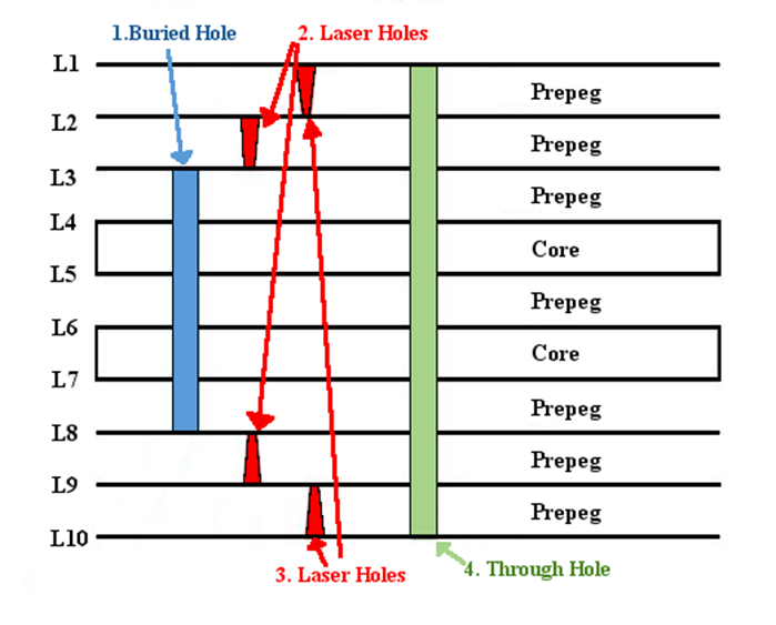
Design Limitations of Blind and Buried Vias
Three thermal press cycles are the maximum that is specified by Underwriters Laboratories. Therefore, for maximum reliability and quality we cannot produce multi-layer boards that require more than 3 lamination steps. What this means is you may not design vias in such a way that it would take more than 3 steps to assemble them. This is a concern when dealing with boards of more than 6 layers. For example, the 10-layer board in the image below would require 2 lamination steps. The first step being layers 3 to 8, after which the buried hole would be drilled and plated. Then in the second step the remaining layers would be laminated after having their laser holes drilled and plated on the layer sets. Finally, the through holes would be drilled and plated which is not a lamination step. Therefore, the board below would have 3 drilling steps but only two lamination steps.
Some other design constraints to consider are as follows:
- We at Bittele Electronics can fabricate micro-via with a size ranging from 4mil (0.1mm) to a maximum size of 6mil (0.15mm).
- Later lamination cycles will plug all BBV holes with epoxy.
- After every lamination cycle, the ability to register drilled holes to inner layers is affected.
- Plated through-holes and Blind/Burried holes must be listed separately on the drawing’s hole chart.
- Annular Ring Minimum: Drilled prior to the first press cycle – 0.1 mm on each side
Related Articles:
Please briefly describe the information you are seeking in the search bar below.