


 English
TURN-KEY PCB ASSEMBLY: BITTELE ELECTRONICS
PCB MANUFACTURING AND ASSEMBLY
Full Turn-Key PCB Manufacturer
You can quickly get quotes and order PCB fabrication and assembly using our online system. Take advantage of exclusive automatic discounts with our tool. Our BOM pricing tool ensures you receive the lowest price for your order.
START A TURN-KEY PCB ORDER
Impedance Controlled Printed Circuit Boards (PCB)
Bittele Electronics provides stack-up and impedance calculations free of charge upon request. Our Field Application Engineers are ready to help you at anytime, whether you just need some advice to design your own Controlled Dielectric, or you prefer to leave the full stack-up creation to us. We will work with your engineering team at the conceptual level of the PCB design to help you obtain better results in controlling impedance by selecting the proper PCB Laminate Material and Multi-Layer PCB Stack-Up.
Bittele's Stack-up Capabilities include:
- Free Stack-up
- Free Impedance Calculation
- Hybrid Build
- RF, Microwave, and other High Frequency PCBs
Bittele Electronics keeps common materials in our in-house inventory at all times. The common materials include:
- Higher copper weights: 2 oz, 3 oz; Heavy Copper PCBs (With Lead Time)
- Odd copper weights: H/1 oz, H/2 oz, 1/2 oz
- Foil: 1/4 oz, H oz, 1 oz, 2 oz, 3 oz
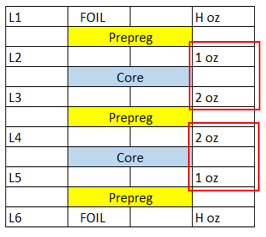
Consideration for Selecting Foil-built or Core-built PCBs
At Bittele Electronics, our usual preference is for Foil-Built PCBs in order make the most economical PCB. That being said, our PCB Assembly Process is very flexible, and we can utilize Core-Built PCBs as well. Foil-Built PCBs not only tend to be more economical than Core-Built PCBs, but they are also slightly easier to process. The pictures below illustrate the difference between the Foil-Built and Core-Built PCBs.
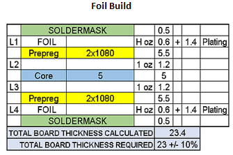
Foil-Built PCBs utilize 1 less core than the Core-Built PCBS in the stack-up. The outside consists of Aluminum Foil. In addition, Foil in different copper weights is much easier to acquire. Since Foil-Built PCBs are made of aluminum, they can be used on any builds, regardless of the primary laminate material being used. Pre-pregs are also less costly than cores, especially if the core is 5 mil or thinner.
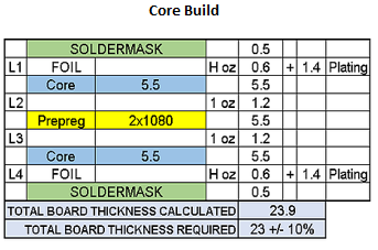
Core-Built PCBs have cores on the outside, so there is no need to use Aluminum Foils. Depending upon material availability, at times it may be difficult to acquire a core with uneven copper weights. This forces the PCB manufacturer to etch down the cores, which is costly since a good deal of labor is involved. Aside from labour, the PCB manufacturer must use a higher copper weight than what appears on the board, increasing material cost as well.
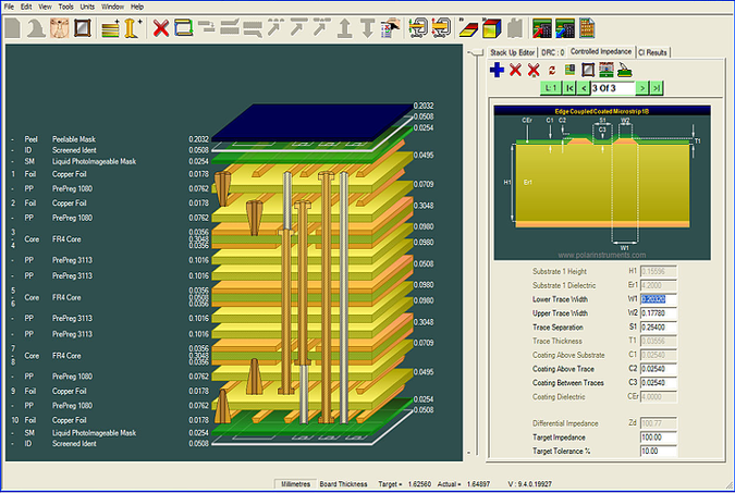
Impedance Calculations
Bittele Electronics uses the industry standard Polar Impedance Calculator SI8000 to calculate impedance. We provide an impedance report and serialized TDR coupons with each shipment free of charge. Typically, designers use published prepreg values from the data sheet to calculate impedance. We have done extensive research over the years to find our "out or press" prepreg thickness, also known as the squeeze-out thickness. Using these values help us refine our impedance calculations so they are closer to actual values on the finished PCB. This is why we encourage you to work with our team and experienced Field Application Engineers at conceptual level so that we can help you refine your impedance calculations.
We run all manufacturing panels with at least 2 TDR coupons placed diagonally across the panel. Both coupons are serialized to panel and array (if present). As mentioned above, we provide serialized TDR coupons & reports with all of our shipments free of charge.