Counting Through Holes Using Gerbers and the BOM (SMT pads included)
See the detailed instructions on counting the number of SMT components using Gerber files.
There are two methods that we use at Bittele to count the number of Through-hole components in your project.
From The Gerbers
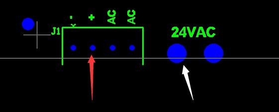
To count the number of Through-hole components, we will be using the top and or bottom outline layers and the drill files. Please note that if your project does have multiple drill files, we will only be using the Top-Bottom set of drill files. This will have the extension “.txt” most of the time.
Once the appropriate outline and drill layers are selected, we can begin counting the number of through-holes for the project. Holding down the shift key will enable us to select each hole individually. If there are several through-holes and individually selecting them maybe a bit tedious, we can go to the “Select” menu and click on the “Selection tool”. When doing this be careful not to select random holes. It is important to note that we are only selecting the holes that will have through-hole components and are found within the outline layers. All other holes will not be considered.
 Figure 1: An Example of what would be considered a Through Hole component (Red Arrow) and what would not (White Arrow).
From The BOM
The number of Through-hole / SMT components can also be calculated from the BOM as well. To do this effectively, the first step will be to hide all the unnecessary BOM columns and begin by creating 4 columns. The first column will be for the number of SMT pads that the component has. The following column will be for the total number of components multiplied by the number of pads it has, which will be discussed shortly.
This should then be repeated for through-hole parts. We can then begin entering the number of SMT Pads or Through-hole positions the part has. If the component is a SMT component, then the hole count can be “0” and vice versa. At this point, the BOM should look something like this.
 Figure 2: Organizing a BOM to count the number of Through-hole and SMT components.
To find out the correct number of pins/pads a component has, we can go on to Digi-Key and enter the part number on the website. We then can review the component information to determine how many Through-hole pins/Pads it has.
After we have done this for all the lines in the BOM, we can begin filing out the second column that we created. In the second column, we will multiply the adjacent cell (which includes the total number of holes for the component in the selected row and multiply it with the quantity for that row. We can then drag the cell so It will autofill all the rows on the BOM.
Finally, we will make a formula below the last cell on the BOM which will be a sum of all the rows above it. This will give us the total count of through-hole components in this project.
Counting the number of through-holes using this method is more accurate then going through the Gerbers.
For more information and for any questions or concerns, please email us at sales@7pcb.com.
Related Articles:
- How Bittele counts the number of SMT pads in your project
- Through hole device assembly
- Through hole assembly
- SMT and Through-Hole Soldering Processes
- How To Design Cost-Effective PCBs
Search articles:


